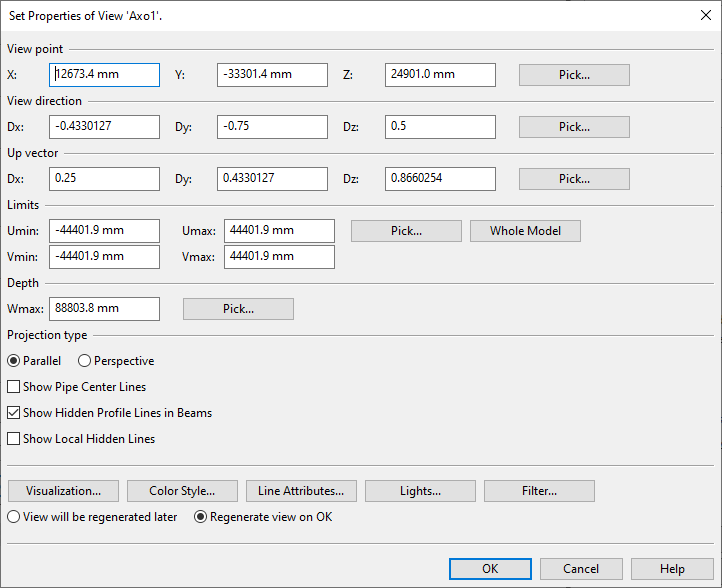
Set Properties of View
In the Set Properties of View <name> dialog, you can modify the properties of the specified view. You can open this dialog from:
-
Views > [view] > Properties
-
Drawing Views > [view] > Modify > Advanced view properties
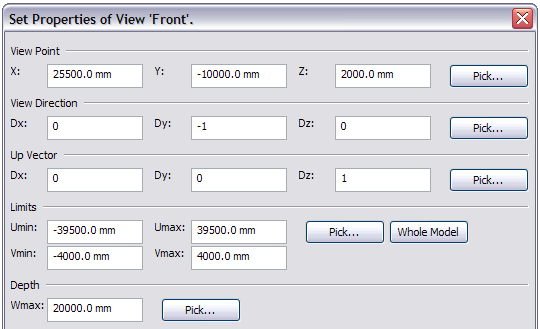
View box
The view box defines the space (limits U, V, and W) visible in the view.
-
View point defines the camera location.
-
Limits define the horizontal (Umin, Umax) and vertical (Vmin, Vmax) boundaries of the view, relative to the viewpoint. The default values are set symmetrically to the viewpoint.
-
Depth defines how far you can see in the view.
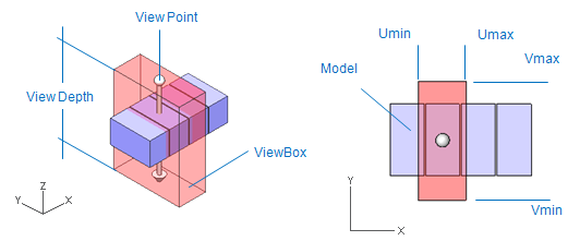
You can move the view box during a command. See Moving the view box.
Note: Home > Views > Fit view limits updates the view box.
When you start modeling, the view limits are usually set according to the design area limits, or they are defined by digitizing a 3D box, and the view limits are the same in every view at this point. Afterward, these limits can be redefined individually in each view.
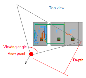
View point
View point is the point where the user is observing the model. Enter coordinates or click Pick in the View Point section to select a point in the model. The cross-hair with a box in front of it is your viewing position. When selecting a point in the model, you can toggle between the open views.
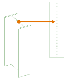
View direction
View direction is the direction from the viewpoint to the viewer.
Click Pick in the View Direction section, and you can see a white box representing the area you'll be able to see in your finished view. On one side of the box there is a cross-hair representing your position. From the cross-hair a line comes out of the box. This line shows the direction you are looking from. Moving the mouse will rotate the box and the line around the cross-hair.
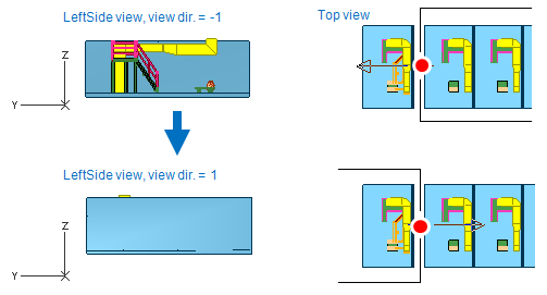
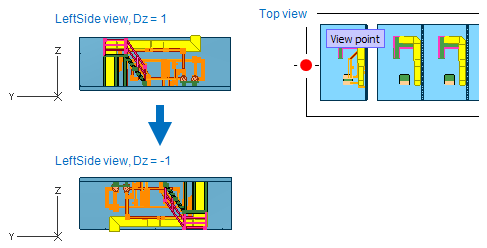
When entering the direction as numbers into the fields, you are specifying from where you are looking. For example for top view other values are 0, but Dz = 1.
Up vector
The 'Up Vector' sets what direction points upwards in your view. You can see this also in the lower left corner of the view in the Axes Marker.
Limits
Limits define the size of the box you'll be able to see in your view. Enter values or click Limits to set a suitable size for the box in the model.
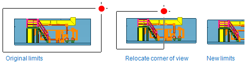
Limits will adjust the sides of the box. Move the mouse cursor near a corner and press Space or click to grab it. Move the corner to the place you want it and press Space or click again to accept.
Depth
The depth defines how far you can see from the viewpoint.
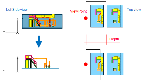
Click Pick in the Depth section, and the mouse automatically grabs the backside of the box (or the limit to how far you can see). Move it to a suitable position and press Space.
Click Whole model to automatically set the box to contain the whole model.
Projection type
Parallel projection
The location and orientation of the view coordinate system {u,v,w} in the global coordinate system {x,y,z} is defined by a point and two direction vectors. The point gives the location of the viewpoint, i.e., the origin of the {u,v,w} coordinate system. The first direction vector defines the view direction which is the positive direction of the w-axis. The second direction gives the positive v-axis ("view-up"). The u-axis and v-axis are in a plane defined by the viewpoint and the view direction which is normal (perpendicular) to the plane. This plane is called the view plane. When the view is displayed on a graphics display the u-axis points horizontally to the right and the v-axis points vertically up.
Objects inside or partially inside the view box are projected onto the view plane. The view box is limited in the w direction by the view plane and a back plane. The back plane is parallel to the view plane and located at a selectable distance (the view depth) from the view plane in the negative direction of the w-axis. A rectangular window defines the location of the view box in u-v coordinates. The lower left and upper right corners of the window are specified by umin, umax, vmin, and vmax values.
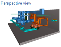
Perspective projection
If a wireframe view uses perspective projection, then the center of projection is located on the w-axis at a given distance from the view origin. Also the view box becomes a view pyramid. The center of the projection is at the tip of the pyramid. View limits (umin, umax, vmin, vmax) specify where the view pyramid intersects the view plane.
If a shaded view uses perspective projection, then a view angle is determined instead of u-limits of the view:
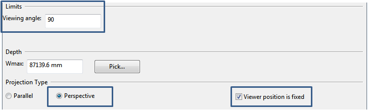
Viewer position is fixed
When a shaded view is set to use perspective projection, then the viewer position can be fixed. In that case the values of the viewpoint actually specify the viewer position. Distance to the center of projection from the viewer position is computed automatically based on the view angle. The fixed viewer position is the center of rotation during 3D digitizing. This can be especially useful when working with point clouds since user can set the viewer position to match the point cloud scanner's coordinates and thus the digitized view appears rather realistic. If the view box is moved while the viewer position is fixed, then the viewer position is moved accordingly.
Fixing the viewer position is also handy for browsing the model. In that case the “camera” stays in place while you rotate. If viewer position is not fixed then your current position specifies the target around which the camera rotates. If you use commands that move the view box then it is the fixed viewer position that is moved.
Show Pipe Center Lines
Select the Show Pipe Center Lines option if you want the centerline of pipes to be drawn in wireframe work views and drawing views, using the Center Lines linetype defined in Line Attribute Styles. After selecting the option, you can define what is the smallest nominal size that causes the line to be drawn.
Show Hidden Profile Lines in Beams
Creating or regenerating a wireframe work view or drawing view performs automatic line removal so that objects only display those edges and surfaces that are visible from the viewing direction of the view. If the Show Hidden Profile Lines in Beams option has been selected, the line removal operation re-draws beam profile lines that are located behind the visible surfaces of a beam part, using the Center Lines linetype defined in the Line Attributes of the wireframe work view or in the Line Attribute Styles of the drawing view.
Tip: Project administrator can select whether this option is enabled or disabled by default, as described in Beams.
Show Local Hidden Lines
Creating or regenerating a wireframe work view or drawing view performs automatic line removal so that objects only display those edges and surfaces that are visible from the viewing direction of the view. If the Show Local Hidden Lines option has been selected, running the Remove Hidden Lines command re-draws those lines that are located behind the visible surfaces of an object, using the Hidden Lines linetype defined in the Line Attributes of the wireframe work view or in the Line Attribute Styles of the drawing view. This operation is applied to all object types except beams.

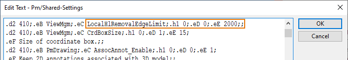
If the option has been selected and a linetype is defined for hidden lines but running the command does not draw the local hidden lines of an object, ask your project administrator to increase the value of "LocalHlRemovalEdgeLimit" (.eE) in the Shared settings configuration object. The default value is 2000.
Visualization / Color Style / Line Attributes / Lights / Filter / Markings

These buttons are explained here in more detail.
Visualization
Visualization Parameters
Visualization parameters determine the accuracy of the visualization.
Most of the visualization parameters are concerned with substituting a simplified view for objects that are too thin or small to be seen in the full detail. This helps to save time that would be wasted in drawing details that would not be seen in the final drawing anyway. These will probably not need to be reset unless some unusual viewing situations arise.
-
Maximum distance between arc and line segment: Curves are drawn as a sequence of straight lines. The number of lines used depends on the size of the circle and the allowed limit on the deviation from a true circle. The circles can be given a smooth appearance by setting the "Max distance between arc and line segment" parameter to a value too small to be seen.
-
Maximum number of line segments in any circle: This is upper limit to the number of lines used in any circle. There may also be a system-imposed upper limit to the number of lines allowed per circle. For fastest drawing the number of segments should be limited; circles with eight to twelve sides are usually acceptable for temporary views.
-
Minimum radius for cylinders: This defines the smallest cylinder that is drawn as double lines. Cylinders with smaller sizes are drawn as single lines.
-
Minimum length for cylinders: If the cylinder is thinner than the given value, it is drawn with a single line along the edge.
-
Minimum radius: This defines the smallest radius for toroids, cones, dishes, etc. that are drawn as double lines, smaller sizes are drawn as single lines.
-
Minimum thickness for flanges: If the flange is thinner than the given value, it is drawn with a single line along the edge.
-
Minimum thickness for plates: If the plate is thinner than the given value, it is drawn with a single line along the edge.
-
Visualization mode for beams: The value is 0 or 1. With the value 0, beams are drawn as beam outlines, and set to 1 to show both the top and bottom edges of the plates making up the beams.
Line Attributes
Each picture segment has a separate set of line attributes for visible edge lines, hidden edge lines, and center lines. Hidden edge lines are lines that have been found to be hidden by other picture segments when hidden lines were removed. The center lines differ from the edge lines in one respect: a picture segment can't hide its own center lines. This feature is utilized to visualize center lines of pipes.
The pattern length of dashed lines can be freely selected. Whether or not the display or plot device can really change the length is hardware dependent.
Changes made to the line attributes are not visualized until the view is re-drawn.
Define line attributes for the following three lines:
-
Visible lines
-
Hidden lines: If you want that hidden lines are not visible, don't select any line type.
-
Center lines
Define following three attributes for every line:
-
The width of line: Select this from the selection list. Line widths are defined in COS.
-
Line type: Select this from the selection list.
-
Pattern length (enter this as mm): This value is for dashed lines.
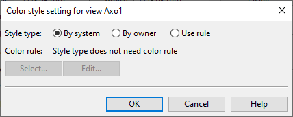
Color Style
You can set model objects in work views to be colored based on their system, their current owner, or surface shading rules. The default color style is defined in the user settings, as described in Colors.
-
By system – Select this to color the objects based on the System they use. For information on defining system colors, see Creating systems.
-
By owner – Select this to color the objects based on who owns them. For more information, see Color objects by ownership.
-
Use rule – Select this to color the objects based on a Surface shading style.
-
Select – Opens a list of available surface shading styles for selecting which style to use.
-
Edit – Opens the current style for editing.
-
Lights
Filter
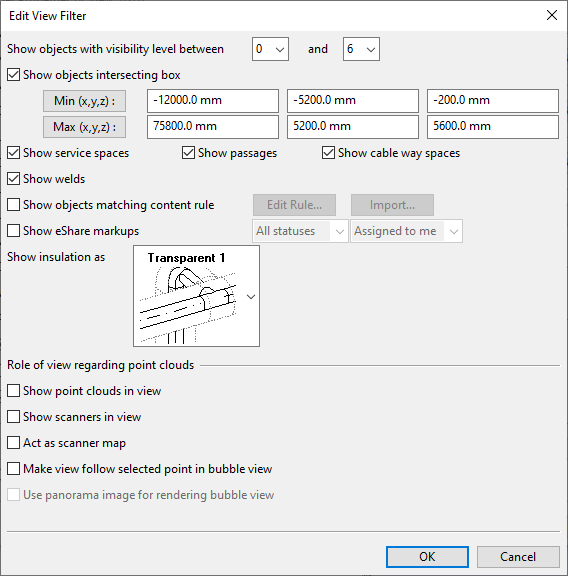
The Filter button opens the Edit View Filter dialog where you can define settings for the visual appearance of the view.
-
Show objects with visibility level between – Select a visibility level range for the view. A model object is visible in a view if its visibility level is less or equal to that of the view. See Filtering views by object visibility level.
-
Show objects intersecting box – Selecting this option creates a filter box in the view. This is an axis-aligned box that contains the entities to display in the view. Only 3D model objects that intersect or are fully contained in this box are shown in the view. If the view displays point clouds, then only the intersecting parts of point clouds are shown in the view. To define the extents of the filter box, specify the X, Y, Z coordinates manually or using the pick tools:
-
Min (x,y,z) – Select this to pick the lower-left corner of the filter box from the 3D model.
-
Max (x,y,z) – Select this to pick the upper-right corner of the filter box from the 3D model.
-
-
Show service spaces / passages / cable way spaces / welds – Select which of these to visualize in the view.
-
Show objects matching content rule – If selected, a content rule is enabled for the view. A content rule is a model query that specifies which 3D model objects are visualized in the view and which are not. 3D model objects that match the query are visualized in the view.
-
Click Edit Rule to edit the view's content rule. See Advanced queries.
-
Click Import to import an existing content rule from COS or from a file. The selected rule is copied as the view's content rule.
Note: If the view filter specifies a content rule, then that and only that specifies what is visible in the view.
-
-
Show eShare markups – If using eShare integration, markups that are linked to Equipment Position Id, Instrument Position Id, or Valve Position Id can show a markup icon and HUD information in the view.
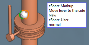
If you enable the setting, you can define these filters:
-
Status: Select whether to show the markup icon for All statuses or just for those markups whose status is New, Approved, Disapproved, or Done.
-
Assignee: Select whether to show the markup icon for All markups or just for those that are Assigned to me.
Note: After enabling or disabling the setting, you must load markups from eShare to update the view.
-
-
Show insulation as – Select how to show the insulation of ducting, piping, and CADMATIC Hull parts in the view.
-
Transparent 1 (default) – The insulated object is visible through the insulation but objects behind the insulation are not.
-
Transparent 2 – Insulation is completely transparent.
-
Opaque – Insulation is opaque.
-
Don't Show – Insulation is not shown in the view.
-
-
Role of view regarding point clouds
-
Show point clouds in view – If selected, the view shows point clouds that are marked as active and intersect with the view box. This option is only available for shaded views.
-
Show scanners in view – If selected, a ball is shown in the view for all scanners that have location information. This option is available for both shaded and wireframe views.
-
Act as scanner map – If selected, the view shows the location of each scanner and also the status of the scanners. The scanner ball color indicates the scanners status. The colors have the following meaning:
-
a red ball indicates that the point cloud for the scanner in question is active
-
a yellow ball indicates that the point cloud for the scanner in question is inactive
-
a green ball indicates the scanner of the active bubble view
This option is available for both shaded and wireframe views.
-
-
Make view follow selected point in bubble view – If selected, the view will automatically move to the location of the point that is picked from a point cloud in a bubble view. The filter box for the view specifies the limits of the area shown around the picked point. The view will show all active and inactive point clouds that intersect the view box. This option is only available for shaded views.
Note: Setting this option will automatically enable the view filter box if it is not enabled. If automatically enabled, the filter box size is set to 2m x 2m x 2m.
-
Use panorama image for rendering bubble view – If selected, the bubble view is rendered as a 3D panorama image computed from the point cloud. This option is only available for bubble views, and it is enabled by default. If the scanner data used by the view is not an evenly distributed 360-degree scan and the panorama image appears to be pixelated, clear the option to render the bubble view as points.
-
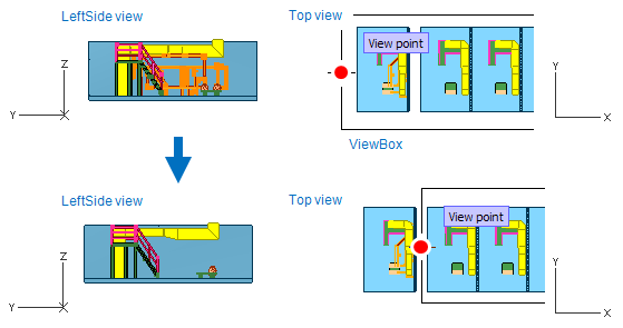
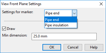
Markings
The Markings button of view properties opens the View Front Plane Settings dialog where you can select whether pipe ends and pipe insulation should display a special pattern when the front plane of the view cuts the objects.
The settings only apply to 2D wireframe views; insulation markings are not shown in axonometric or shaded views.
-
Settings for marker – Select "Pipe end" or "Pipe insulation".
-
Draw – If selected, the marking is shown when the object is clipped by the front plane.
-
Min dimension – Specifies the smallest nominal size that should display the marking.
In this example, on the left the markings are disabled, and on the right they are enabled:

Note: These markings can also be enabled for Plant Modeller drawings. Select Views > Drawing Views from the context menu of a drawing, and then click Markings.
View regeneration

Select how to regenerate the view:
-
Regenerate view later – Select this option to regenerate the view later, for example, via Views > Regenerate.
-
Regenerate view on OK, visualize all components (by content rules) – Select this option to allow the view to be regenerated when you close the properties dialog. This option re-visualizes all components according to current content rules. If no content rules are defined, everything will be visualized.